
Including Reference Plane Edges from Peer Parts

To include Reference Plane or part edges from Peer parts in the part you are designing, you need to be editing that part in the context of an assembly. This is achieved in one of three ways:

  1. Create a new part "in place".
  2. Double click on a component part (In Place Activate).
  3. Right click on a component part and choose "Edit".

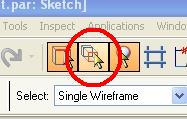
Once this is accomplished, you will also need to insure the command "Peer Edge Locate" is active (shown at left).

If the Reference Planes on the Peer part are not shown, you can use the Assembly Select Tool (found under the Tools menu) to turn them on.

Comments

Popular posts from this blog

Solid Edge ST3 - Part 1 of 4

The Siemens PLM Connection event is over.  Given the change of date and venue due to the flooding of the Opryland Hotel in Nashville, it was a great success.  There were many excellent presentations and "hands-on" training sessions for Solid Edge (including mine) , and even though a formal announcement of the upcoming ST3 is some time away, we got a sneak peak of several new customer driven enhancements as well as some hint of: A "bridge" to help existing users better adopt Synchronous Technology Simulation enhancements PDM enhancements 1000's of customer enhancements from modeling to the user interface Over the next few weeks, I'd like to cover some of the items presented around the customer driven enhancements, but please keep in mind there are still a whole lot of items that will not be presented until the official Solid Edge ST3 launch later in the year. For this post, I would like to cover the User Interface enhancements. You now have...

Dimension Projection Line Breaks

Often when placing dimensions on drawings, the projection lines of some dimensions will cross the projection lines of other dimensions as shown below. Solid Edge provides a function to automatically create breaks in one extension line where it crosses another. This function is called "Add Projection Line Break". It is accessible from the Shortcut Menu when you have a dimension highlighted. The result is shown below. If you wish to remove the projection line break, highlight the dimension, invoke the shortcut menu, and select "Remove Projection Line Break".

Solid Edge V20 Deployed!

I have finally gotten Solid Edge V20 and the Viewer deployed through my organization on Sept. 27th. We deploy SE to over 100 users and the Viewer to over 400 users across about 10 geographic locations in one night over a couple hours. All went well considering this was the first deployment since the new Packaging Specialist started, and it was done on a brand new version of the deployment system we use. We use Microsoft's System Center Configuration Manager (SCCM) which was just upgraded from SMS 2003. http://www.microsoft.com/systemcenter/configmgr/default.mspx . It allows inventorying PC's throughout the org, as well as pushing software to the PC's. To be able to push the software, you must use the MSI supplied by Solid Edge and repackage it as an EXE. Since the MSI is used, you must also install .NET and ISSCRIPT separately (which can also be added to the EXE package). We found that the ISSCRIPT.MSI must be modified to work with SCCM due to the fact that it insta...