To pull Solid Edge hole or thread information from a model that has been placed in a drawing, you can use the Callout command.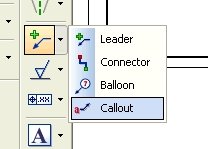
The Callout command provides several Hole Reference "code" buttons to allow automatic extraction of the hole or thread information. Hovering over each will explain what it is for if you can't get the hint from the graphic on the buttons. You will also notice a Hole Callout "code" button. That is explained below.
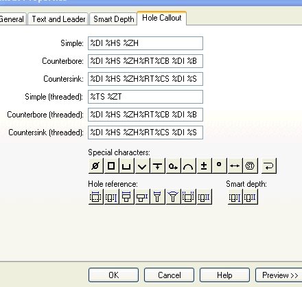
The Hole Callout button inserts a code which allows one Callout to annotate the 3 types of holes (with or without threads). It uses the information on the Hole Callout tab from the line specific to the type of hole your annotating. Each line contains the codes for several of the Special Characters and Hole Refernce buttons and are formulated for the specific type of hole they are meant to depict. These can be set up/changed from the Style form found under the Format menu. To make these available in all new files, make the change in your template file.
Comments