Solid Edge V19 can open AutoCAD files up through version 2004. To open them, all one must do is start Solid Edge, invoke the Open command, change the Filetype to DWG, and select the file.
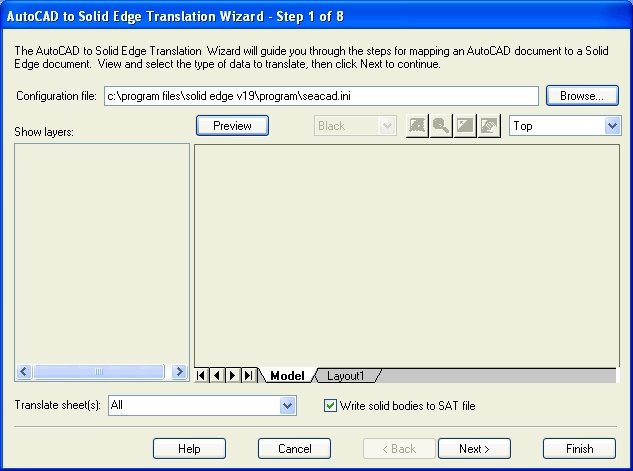
Solid Edge also has a wizard based option form that allows you to configure how the AutoCAD file is converted. To access the options, select the desired DWG file with a single click and the Options button found on the lower left of the Open form will become active. Click it.
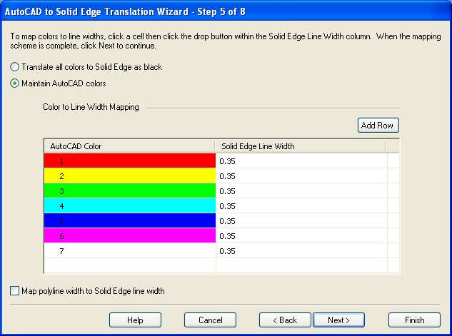
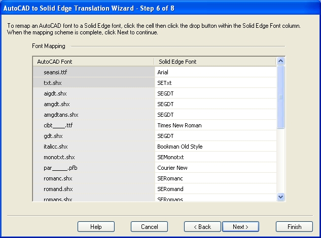
The Options form consists of 8 pages that deal with specific translation options such as DWG element color to SE line width mapping, hatch mapping, font mapping, etc... All of these settings are written to an INI file, and multiple INI files can be kept and a different one specified for specific translation jobs if desired.
The Siemens PLM Connection event is over. Given the change of date and venue due to the flooding of the Opryland Hotel in Nashville, it was a great success. There were many excellent presentations and "hands-on" training sessions for Solid Edge (including mine) , and even though a formal announcement of the upcoming ST3 is some time away, we got a sneak peak of several new customer driven enhancements as well as some hint of: A "bridge" to help existing users better adopt Synchronous Technology Simulation enhancements PDM enhancements 1000's of customer enhancements from modeling to the user interface Over the next few weeks, I'd like to cover some of the items presented around the customer driven enhancements, but please keep in mind there are still a whole lot of items that will not be presented until the official Solid Edge ST3 launch later in the year. For this post, I would like to cover the User Interface enhancements. You now have...
Comments